MF0026 – Installation Notes
MF0026 – EJ EH Premier Preslite Windscreen Washer Pump Diaphragm Installation Notes
The Information on this page has been taken directly from the EJ EH Holden factory workshop manual and is not the opinion of Mad Folk Engineering. The following information should be used as a guide only.
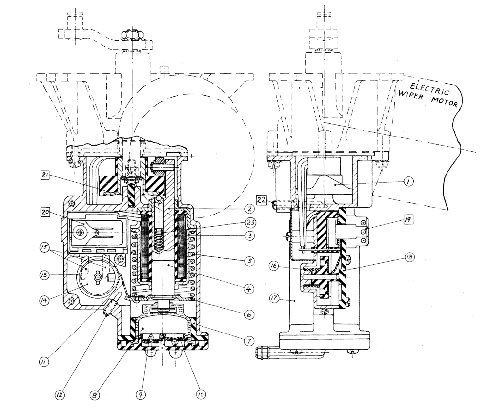
Fig. 12F-12
SECTION VIEW OF PRESLITE WIPER AND WASHER ASSEMBLY
|
|
Two-Speed Windshield Wiper and
Washer Assembly ‐ PRESLITE
In Production the 235A Premier model is equipped with a Preslite two speed windshield wiper motor and washer assembly. The washer pump assembly is bolted to the wiper motor drive shaft housing and is driven by a nylon cam attached to the driveshaft extension.
The attachment of the two speed windshield wiper and washer assembly to the front face of the dash panel is the same as the single speed windshield wiper motor assemblies fitted to all other models. For removal and installation instructions and details of wiper linkage, refer to Section 1 Body.
Service procedures for both components are included in this Section. The two speed Preslite windshield wiper motor is similar to the single speed except that an additional field winding is provided to give two speed operation.
Washer Pump Operation
During normal operation of the windshield wiper motor, the washer unit pump mechanism is in the idling position. When the button in the centre of the wiper control knob is pressed the washer pump solenoid is energized and engages the pump which operates a full cycle of the automatic timing mechanism. On completion of the cycle, the washer pump returns to the idling position, and the motor must be turned off manually after the washer operating cycle has finished. If the button in the centre of the wiper control knob is pressed whilst the wiper motor is “Off ” the wipers are automatically turned on to the slow speed position. The wiper motor high speed position of the control knob must be manually selected.
Disassembly Washer and Wiper Assembly
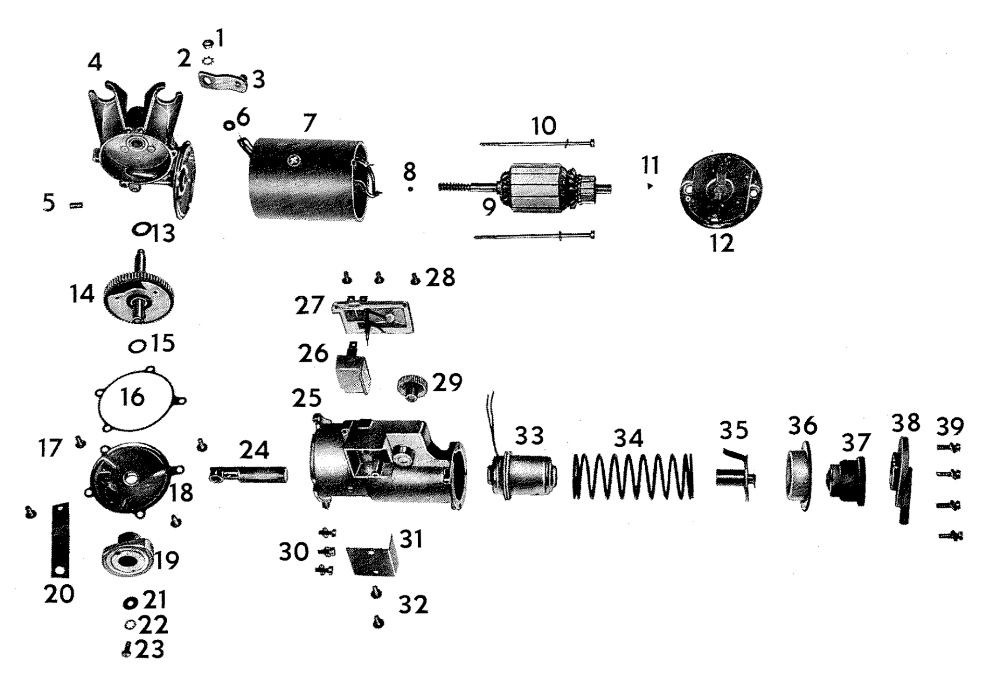
For identification of parts refer to Fig. 12F-12 and 12F-15
- Remove assembly from vehicle.
- Remove the two screws retaining junction box cover plate and unsolder all wires from terminal posts.
- Remove the three attaching screws from the plastic terminal plate and remove terminal plate.
- Remove circuit breaker assembly taking care not to damage gasket.
- Hold down trip spring blade with small screw driver and withdraw ratchet wheel. (Fig.12F-13).
- Remove the four screws from the pump end plate and remove diaphragm, valve assemblies, plunger and pump spring.
- Withdraw solenoid assembly from pump housing.
- Remove three screws attaching housing to motor assembly and remove housing.
- Remove plunger assembly from nylon cam.
- Remove hexagon head screw from nylon cam and remove cam from cross shaft. (Fig. 12F-14).
- Unsolder wires from terminal plate.
- Remove the cross shaft crank.
- Withdraw insulating sleeves and rubber grommet from motor wires.
- Remove both motor housing through bolts, and withdraw motor assembly from gear case taking care not to lose thrust cone in worm end of armature.
- Remove armature from housing, taking care not to lose the thrust cone from commutator end of armature.
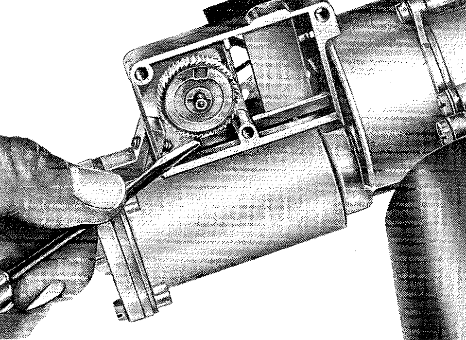
FIG 12F-13
RELEASING PUMP RATCHET SPRING
- Withdraw end plate assembly from motor housing until sufficient clearance is obtained to permit unsoldering field wires.
- To remove brushes, unsolder pig tail.
- Remove gear case cover plate assembly.
- Withdraw cross shaft and gear assembly from housing taking care not to lose thrust washers on either side of the gear.
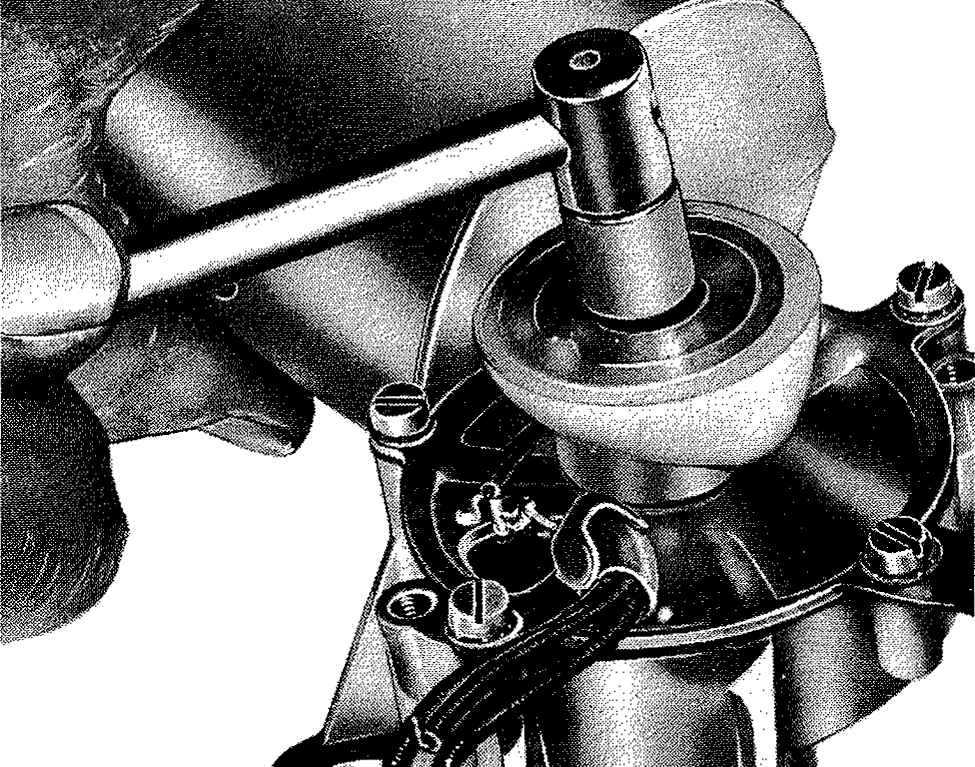
FIG 12F-14
REMOVING NYLON CAM
|
|
Inspection and Test Washer Pump
- Inspect pump diaphragm for damage.
- Check operation of inlet and outlet valves, these can be washed out with light water pressure.
NOTE: These valves are only replaceable with end plate assembly.
- Inspect ratchet gear teeth for wear or damage.
- Hold ratchet gear coil spring between finger and thumb and turn ratchet wheel in anti-clockwise direction, the gear should lock when turned in a clockwise direction.
- Check solenoid for continuity or short circuit.
- Check plunger for free fit in solenoid barrel.
- Check spring loaded plunger return plunger for free fit, and spring collapse. (The plunger and cam follower can only be replaced as a complete assembly.)
Assembly
Reverse to disassembly operations, noting the following
points :
- Install one thrust washer on each end of gear and cross shaft assembly and install assembly in gear housing.
- Repack gear housing to 1/3 of its capacity with recommended lithium base grease.
- Install a new gear cover to housing gasket and replace cover.
- Note that the gear cross shaft splined end incorporates a master spline to facilitate attachment of the drive crank then tighten attaching nut to 4 to 6 Ib.ft.
- Place thrust cone in commutator end of armature.
- Lubricate commutator end of armature shaft with ‘light engine oil.
- Install brushes and end plate assembly on end of armature.
- Install armature and end plate in motor housing, leaving adequate clearance to solder field wires to brush holders.
- Ensure tongue in end plate is indexed with cut out in motor housing.
- Lubricate worm end of armature shaft with light engine oil, then place thrust cone in end of armature shaft.
- Offer up the motor housing assembly to gear housing at the same time insert field wires through the hole in gear housing; also ensure the tongue in motor housing is indexed with the cut out in the gear housing.
- Install the motor housing through bolts.
- Install rubber grommet and insulators over field wires.
- Resolder field wires to terminal on gear cover.
- Install nylon cam to cross shaft.
Assembly ‐ Washer Pump
- Install solenoid in pump housing and at the same time thread both wires through slot in junction box, also ensure that slot of solenoid is in line with slot in pump housing (Fig.12F-16).
- Replace pump spring in housing.
- Install diaphragm assembly to pump end cover.
Note: For ease of assembly, the rubber diaphragm may require dipping in water.

FIG 12F-16
ALIGNING SOLENOID WITH SLOT IN PUMP HOUSING
- Place pump end assembly on pump spring, so that the rivet of the spring blade does not ride on the last coil of the pump spring and with the hose outlets away from the motor body. (Fig.12F-17).
- Compress the spring and end assembly by hand then install the four screws and tighten evenly; taking care not to distort end cover.
- Hold down trip spring blade with small screw driver and install ratchet wheel refer (Fig. 12F-18).
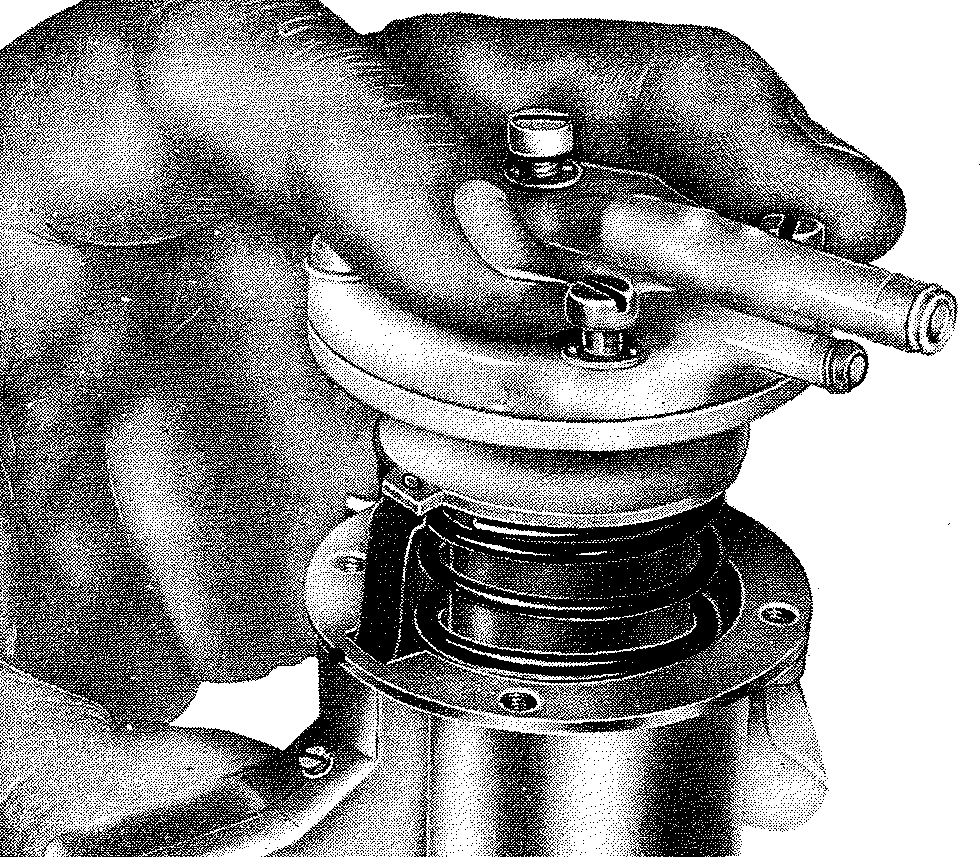
FIG 12F-17
CORRECT POSITION OF PUMP SPRING COIL
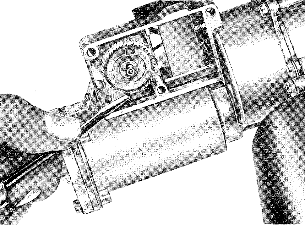
FIG 12F-18
INSTALLING RATCHET WHEEL
- Install circuit breaker.
- Replace terminal plate and install the three screws.
- Install plunger assembly into barrel of solenoid.
- Thread the three wires from the motor assembly through the aperture in the pump housing, then engage pump plunger with the nylon cam Fig. 12F-19)
Note: Care should betaken before proceeding with the following step to ensure the rubber grommet is correctly located in the pump housing.
- Install the three pump housing to motor assembly attaching screws then tighten.
- Resolder wires to junction block (refer wiring diagram Fig. 12F-20).
- Replace junction box cover plate and install both screws
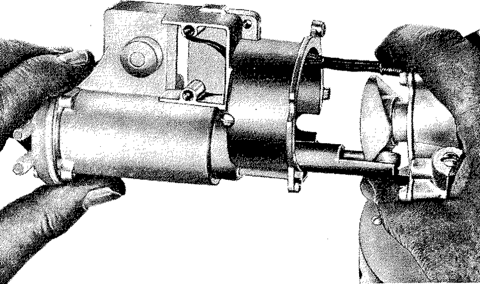
FIG 12F-19
ENGAGING PUMP PLUNGER WITH NYLON CAM
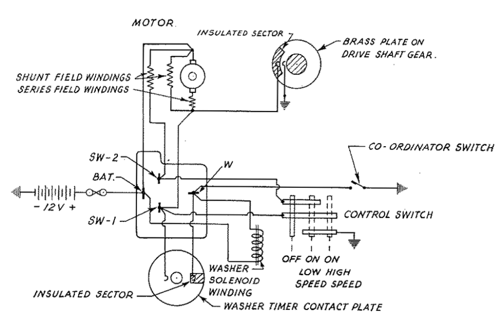
FIG 12F-20
WIRING DIAGRAM ‐ PRESLITE WIPER AND WASHER
Adjustment ‐ On Bench
Provision is made for adjustment of the number of strokes per cycle within a limited range. This is achieved by the adjusting screw(Fig.12F-2o1n) the end of the washer timer housing. Rotating the adjusting screw anti-clockwise increases the strokes per cycle. The recommended cycle is 12-14 pressure strokes of delivery (6-7 motor revolutions)
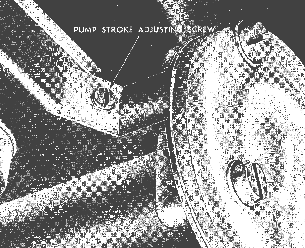
FIG 12F-21
PUMP STROKE ADJUSTING SCREW
Caution: Rotate the adjusting screw a little at a time then recheck number of strokes per cycle, before further adjustment. When adjustment is completed the screw should be locked in position by applying a spot of paint in the screw aperture (Fig.12F-21